Project Overview
6/2/2015
This project is intended to use the lessons learned from the charcoal auto-smoker (still in progress, but potentially in limbo for this summer) so that a simpler, easy to mimic autosmoker can be built.The goal is to end up with a device that can be instructed to maintain a certain temperature over the course of he smoke, and provide email and/or text alerts once the meat is done and/or a timer has run out. All data will be logged, and a large part of this project will be developing a friendly way to display the data on the web interface in real-time and for review.
The device will plug into a 120v electrical outlet, and provide one or two duty-cycled outlets to control one or two heater elements in the electric smoker. The intent is to provide a wide range of temperatures, but it has been observed (especially in cold weather) that with some models of electric smoker, a single heating element does not achieve the desired temperature, even at full duty cycle. Providing an option for a second heating element will allow for higher achievable temperatures, as well as potentially increase the rate at which the internal temperature can be raised (especially useful after smoker has been opened to baste, flip, check, crutch, or adjust meat). For now, a single heater will be used, though, as the wiring and devices used are not rated to handle more than one heater. If required, we can add a second outlet and SSR later on.
This project will be laid out with step-by-step instructions for educational purposes only, and the source code will be made available on GitHub once it is in a usable state.
CAUTION: This project is dealing with 120VAC at potentially lethal levels of current. I can and will assume no responsibility for anyone who follows these instructions. They are provided here for educational purposes only. Do not blame me if you electrocute yourself or burn down your house! This device may be dangerous if exposed to water, moisture, or left unattended. You have been warned!
Hardware, pt. 1
6/3/2015
I ordered a bunch of what I needed for this project last summer. A survey of the hardware shows that I have a little bit left to collect, but much of what I am using is similar or identical to the other auto-smoker project.
The list of what I currently have includes the following:
- Raspberry Pi
- Yocto-Thermocouple (USB/Thermocouple Interface)
- Meat Thermocouple - Auber Instruments WRNK-171S
- Smoker Thermocouple - Auber Instruments TC-K3MM-C
- Solid-state Relay (and heatsink) - FOTEK SSR-40 DA
This leaves a shopping list to include at least:
- Male plug for 120VAC outlet
- 2-port female plug for 120VAC outlet (to plug in heating elements)
- Enclosure
- 2ndary heating element for smoker
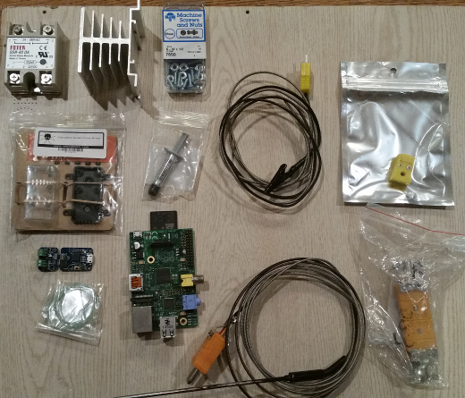
Above: Assorted hardware already on hand
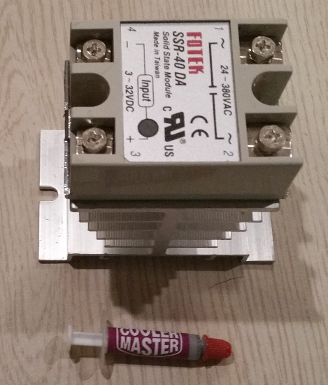
Above: SSR bolted to heatsink. The above heatsink paste was used in between components to ensure proper heat transfer.
Hardware, pt. 2
6/12/15
I had a chance to stop at the hardware store and get most of the rest of what I needed. I picked up a cord with plug, GCFI outlet, and box to house the outlet. Later on, I will need to find build an enclosure to house the outlet and SSR, as I do not want any of the wiring exposed to the elements, or to any fingers that might happen across them. The wiring for the outlet is identical to wiring any standard household outlet with switch, with the exception that the SSR is taking the place of the switch (on the hot wire).
I decided to use a GCFI outlet, as it was highly recommended by the individual that I consulted at the hardware store. To my dismay, when I initially tested the circuit, nothing came on or lit up on the AC side. After a little testing and fiddling, I realized that the GCFI outlet needs to have the "RESET" button pressed in while the circuit is powered. Thankfully, this does not need to be done every time the GCFI outlet loses power, only when it is tripped, and apparently, also when it is first used.
It made sense to test this setup before attaching it to any electronic control system, so I rigged it up so that I could easily do so. As recommended by an article that I found on bench testing SSR's here, I used a light as a load to make sure that it was working, and I used a 9v battery to activate the control side.
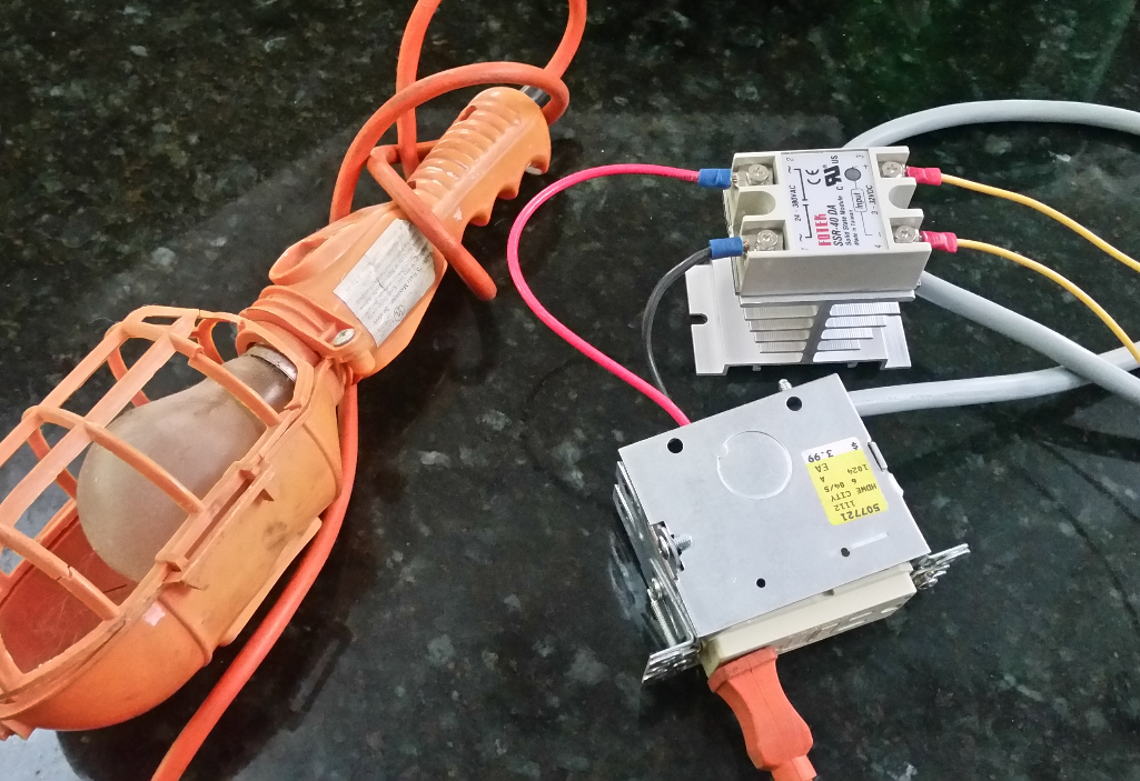
Above: test setup, not powered
After the initial issue with the "RESET" button, everything seems to work okay, though I will use the red wire (powering the box from the SSR) to inductively measure the current during a test run to ensure that nothing overheats or breaks down, and to verify that the heating element is able to pull as much current as it requires. This will be done with a 9v on the control side, and before setting up in an enclosure or attaching the Pi to the control side. Everything tested okay with the load (the work light illuminated), but I found that the outlet and SSR each have lights on them (circled in green, below), which may prove useful for diagnosis later on.
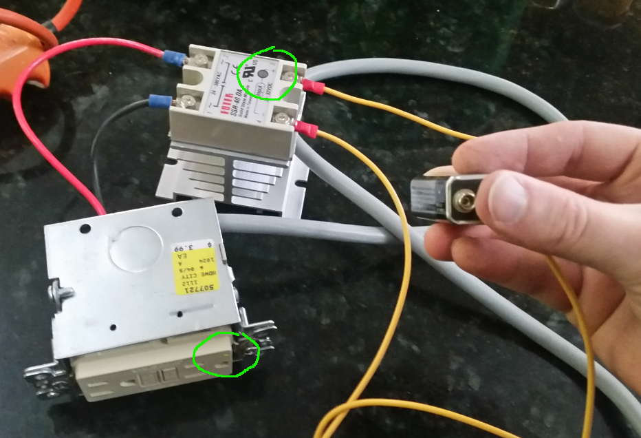
Above: testing with no load, control circuit off (9v detached)
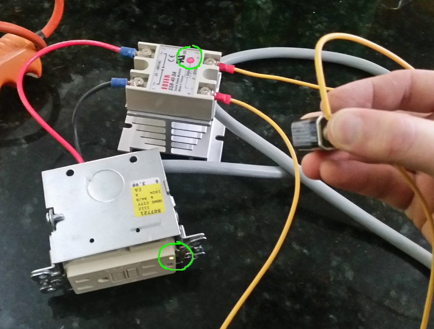
Above: testing with no load, control circuit on (9v attached)
Software, Pt. 1: Configuring the Pi
6/26/2015
This write-up is a bit on the lengthy side, but I ran into more than my share of minor issues during this process. I assume that by providing this information, anyone wishing to mimic my project can do so easier, experienced Linux/Pi user or not.
The first step in dealing with the software is setting up the Pi so that it can be used. I will be developing my code on another machine, and simply copying it over, but the Pi must be configured to run everything. I was tempted to simply copy the image from the charcoal smoker's Pi, but realized that I did not detail any of the setup, and that all of the software on that machine needs to be updated, anyhow.
I am using the newest version of Raspbian, because it is easy and compatible with everything that I intend to use. It is available with instructions here: https://www.raspberrypi.org/downloads/. If you are using a Windows machine to write your image, this process works well: https://www.raspberrypi.org/documentation/installation/installing-images/windows.md.
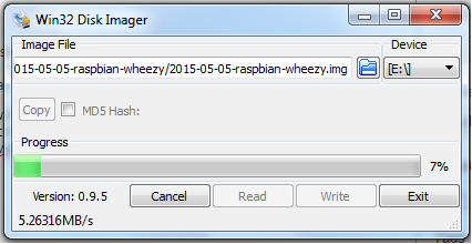
Of course, this image is 3.2GB, and the smallest SD card that I had available was 16GB. In order to make use of the full space, the image will have to be expanded on the card, but this will be handled during the installation process. It should be noted that to login to the command line after initial setup, the default user is "pi" and password is "raspberry", without the quotes.
Hook up the HDMI port, a USB keyboard, and Ethernet cable (connected to your router or access point with DHCP enabled) before attaching the power cable.
Upon hooking the Pi up to a TV or monitor with the HDMI port and powering it up, the configuration menu appears on first boot. This menu provides several options. The first step is to select option 1, Expand filesystem, so that we can be sure that all available space on the SD card is available for our Pi to use. After this, go to the advanced options menu and enable SSH. If you decide not to enable it immediately, or want to change other options later, you can get back into the configuration menu by entering "sudo raspi-config" on the command line (no quotes).
Note: I made the mistake of rebooting immediately after expanding the filesystem, which caused an issue when attempting to enable SSH later on. Skip this if you already enabled SSH! If you run into this problem (you are prompted to wait for an SSH key to be generated, which never completes), you will need to enter the following at the command line: "sudo rm /var/log/regen_ssh_keys.log" (no quotes). Solution was found here: http://raspberrypi.stackexchange.com/questions/1303/do-ssh-failing-in-initial-setup.
After SSH is enabled and any other settings are changed that you want, reboot the Pi from the menu.
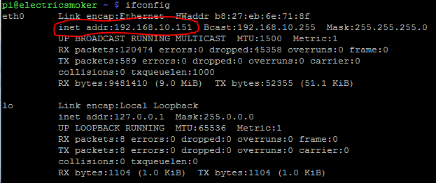
Now we need to connect to our Pi from our PC, laptop, or whatever we are using. Before we can connect to our Pi, we need to see what IP address it is using. On the command line, enter "ifconfig" and the automatically assigned IP address will be displayed (assuming that DHCP is enabled on your router). The IP address listed for eth0 is what we will need to connect to the Pi using SSH. Note that if your router resets or you leave the Pi disconnected or off long enough, the IP address may get assigned to another device on your network later on. It is assumed that your router is connected to the Internet, as we will need to update our installation and install some additional packages.
If you are using windows, download and install Putty. Instructions for using Putty with the Pi are available here: https://www.raspberrypi.org/documentation/remote-access/ssh/windows.md. Of course, you can continue to use the attached video output and keyboard for now, but you will want to be able to SSH to your Pi for later tasks, so you may as well get used to it now.
First thing we want to do on any Linux installation is make sure that everything is up to date. "sudo apt-get update", then "sudo apt-get upgrade".
Next on our to-do list is setting WiFi on our Pi, so that we do not require it to be tethered by an Ethernet cable during operation. If you intend to run an Ethernet cable to your smoker, you can skip this, but being free of as many wires as possible just seems to make sense.
I found a Tenda W311MI WiFi adapter in a bargain bin at the local computer store, and discovered that it is on the Pi's WiFi HCL (http://elinux.org/RPi_USB_Wi-Fi_Adapters), so I will use it. We can either manually configure it, or use wicd. After doing the update above, I ran "sudo apt-get install firmware-ralink" to ensure that everything was installed and up to date for the WiFi dongle that I have. You may need a different package if you have a different WiFi chipset.
- Instructions on how to configure your adapter to automatically connect to your access point or router are found here: http://www.howtogeek.com/167425/how-to-setup-wi-fi-on-your-raspberry-pi-via-the-command-line/.
- If you wish to use a static IP, or need to configure for multiple possible networks, a great example and more information is available here: http://raspberrypi.stackexchange.com/questions/11631/wifi-setup-for-multiple-networks.
- For iffy WiFi spots, having the ability to automatically reconnect to the access point is a must. This should allow your Pi to attempt to automatically reconnect: https://www.raspberrypi.org/forums/viewtopic.php?t=16054.
- The easiest method, however, is to install wicd. Instructions can be found here: http://blog.ubidots.com/setup-wifi-on-raspberry-pi-using-wicd. It appears, though, that wicd drops the Ethernet connection during the configuration/connection process, so you will need to use a keyboard and display directly attached to the device in order to use this method.
Software, Pt. 2: Configuring the Yocto-Puce and Pi to play nicely together
6/28/2015
After searching for an accurate and easy to use solution for temperature monitoring for the charcoal smoker, I stumbled across the Yocto-puce thermo-couple monitor. It can use a variety of thermo-couples, but we will use K-type thermo-couples for this project. Not only did this device seem very straight forward to use with the Pi, but a sample project very close to this one is set up on their site. The instructions for setting up the Pi and Yocto-puce to work together, as well as the sample program from Yocto are here: http://www.yoctopuce.com/EN/article/cook-and-hold-with-raspberry-pi-video. Unfortunately, it seemed that the program that they have there did not work well with long cook times, and there were a number of other changes and goals (including automation) that I had desired, so the only code used from here is the generic python code for talking and listening to the Yocto-puce.
